Time to Failure Module
Given pipe and soil properties, loading and corrosion patch geometry, the Time to Failure Module is capable of predicting the actual hoop (maximum) tensile stress in the pipe. Given corrosion rates, the Time to Failure Model can:
- Predict the time window from current pipe condition to when a failure occurs.
- Determine the critical crack length for a possible burst based on fracture mechanics criterion.
- Determine the type of failure (leak or burst) caused by corrosion.
When a leak rather than a burst occurs, the Time to Failure Module allows the user to further assess the potential burst failure of corroded cast iron pipes caused by pressure transients and determines the time window for leak before break. The Time to Failure Module also incorporates the analysis of uncertainty of key physical parameters and predict the probability of failure and hazard rate over the specified number of years.

Time to Failure Module Workflow
Traffic load (kN):
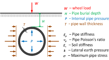
Indicated by the wheel load. Click to see the image A buried pipe under internal pressure and traffic load for more information.
Accepted Values: 0 ≤ W < 100 kN

(Click to see User Manual - Pipe failure analysis for more information)
Accepted Values: 0 ≤ W < 100 kN

(Click to see User Manual - Pipe failure analysis for more information)
Maximum allowable pressure (kPa):
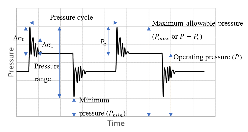
The maximum pressure in the pipe taking into account surge pressure. Click to see the image Pressure explanations for more information.
Accepted Values: 0 ≤ Pmax

(Click to see User Manual - Pipe failure analysis for more information)
Accepted Values: 0 ≤ Pmax

(Click to see User Manual - Pipe failure analysis for more information)
Soil Type:
The soil type names are from AS 4419 (2018). The users can select a soil type from the list and the soil properties will be prefilled. Soil type could be any of the following soils:
Accepted Values: sand, loamy sand, sandy loam, fine sandy loam, loam, silty loam, sandy clay loam, fine sandy clay loam, clay loam, silty clay loam, sandy clay, light clay, silty clay, medium clay, heavy clay
(Click to see User Manual - Pipe failure analysis for more information)
Accepted Values: sand, loamy sand, sandy loam, fine sandy loam, loam, silty loam, sandy clay loam, fine sandy clay loam, clay loam, silty clay loam, sandy clay, light clay, silty clay, medium clay, heavy clay
(Click to see User Manual - Pipe failure analysis for more information)
Advanced Parameters Click to show
Pipe Properties
Soil Properties
Soil modulus (MPa):
An elastic soil parameter used in the settlement, compression or movement of soils. It is the slope of stress–strain curve in the elastic deformation region for the soil.
Accepted Values: 0 < Es < 300 MPa
(Click to see User Manual - Pipe failure analysis for more information)
Accepted Values: 0 < Es < 300 MPa
(Click to see User Manual - Pipe failure analysis for more information)
Lateral earth pressure coefficient:
The lateral earth pressure coefficient at rest and can be calculated by: k = ( 1 - sin∅ ) where ∅ is the soil friction angle.
Accepted Values: 0 ≤ k ≤ 1
(Click to see User Manual - Pipe failure analysis for more information)
Accepted Values: 0 ≤ k ≤ 1
(Click to see User Manual - Pipe failure analysis for more information)
Soil unit weight (kN/m3):
The ratio of the total weight of soil to the total volume of soil. Soil unit weight or bulk unit weight is the unit weight of soil and varies for different soil types. The values are typically between 15 kN/m3 to 20 kN/m3.
Accepted Values: 0 < γs ≤ 30 kN/m3
(Click to see User Manual - Pipe failure analysis for more information)
Accepted Values: 0 < γs ≤ 30 kN/m3
(Click to see User Manual - Pipe failure analysis for more information)

